|
Introduction: A
Cemetery Inside the Grounds of an Auto Plant
A
number of years ago, in the mid-1980s,
General Motors Corporation built
the Detroit/Hamtramck Assembly plant near
the intersections of major
Detroit freeways and major rail lines.
Proximity to
transportation links made sense from a
variety of viewpoints. To
acquire the land for the large new plant
(eventually to cover 362
acres), a combination of deals were employed
(eminent domain, purchase,
and so forth); some met with more favor than
did others
(Wikipedia).
The
Detroit/Hamtramck Assembly
Plant, has extensive security surrounding
it. Figure 1 shows a
secured entrance gate. Figure 2 shows
the general location of the
plant, at the north end of Chene Street, in
the contemporary context of
Google Earth.

Figure
1. Plant entrance and security.
Photo courtesy of Chene
Street History Study archive.

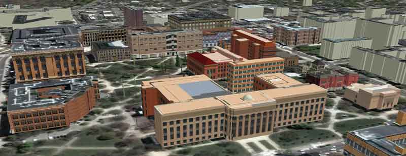
Figure
2. Plant site at the north end of Chene
Street and adjacent
to freeways and railroad tracks.
Take a closer look; the area to the
north end of the plant
contains quite a bit of grass adjacent to
the giant parking lot.
Figure 3 shows a
small patch of trees that appear more mature
than the others on the
plant site. The trees appear walled
into a rectangular area.

Figure 3. Rectangular patch
of mature trees behind a wall.
The patch of trees is, in fact, part of a
cemetery that predated, by
almost a century, the Detroit/Hamtramck
Assembly Plant. General
Motors was not able
to acquire that small patch of land because
of zoning and easement
restrictions already in place in association
with the cemetery.
Figure 4 shows a closer look at the
cemetery.

Figure
4. Cemetery on the grounds of the
Detroit/Hamtramck Assembly
Plant. Note
tombstones. Entrance gate is to the left
of the white car.
Records
in the Chene Street History Study (CSHS) and
elsewhere show that this
cemetery is named Beth
Olem and that it is a Jewish cemetery that
is one of the oldest in
Michigan. It is open for only a few
hours a year, in association
with selected Jewish holidays. To
visit the grave of a loved one,
it is required to enter through GM security
first (Figure 1) and
then through cemetery security which
requires the gates of the walled
cemetery to be open. The walls are 8
feet tall. Naturally,
this high level of security makes it
difficult for visitors to gain
access.
Comtemporary Visualization: Virtual
Beth Olem Cemetery
Google
Earth or other contemporary visualization
technology could make it
possible, however, to overcome the
frustrating security
situation. Imagine a 3D model of the
cemetery, complete with
geo-referenced images/models of
tombstones. Click on a grave
marker and get taken to materials from the
archive (insofar as privacy
concerns permit). Link from the
tombstone to a blog of associated
materials. The process of
building a virtual Beth Olem is
underway. When complete, it will
serve not only to overcome access and
distance issues for loved ones to
visit 24/7, but it will also serve as a
basic study in the systematic
use (by blog associations) of the CSHS
archive, added to the present
'GEOMAT' (Geographic
Events Ordering: Maps, Archives, Timelines;
Arlinghaus, Haug, and
Larimore) methodology.
The archives of the Chene Street History
Study have many photos taken
from inside Beth Olem. The image in
Figure 5 is one example that
shows clearly the proximity of the
industrial complex to the otherwise
peaceful resting ground; the juxtaposition
of the different worlds is
really quite startling.
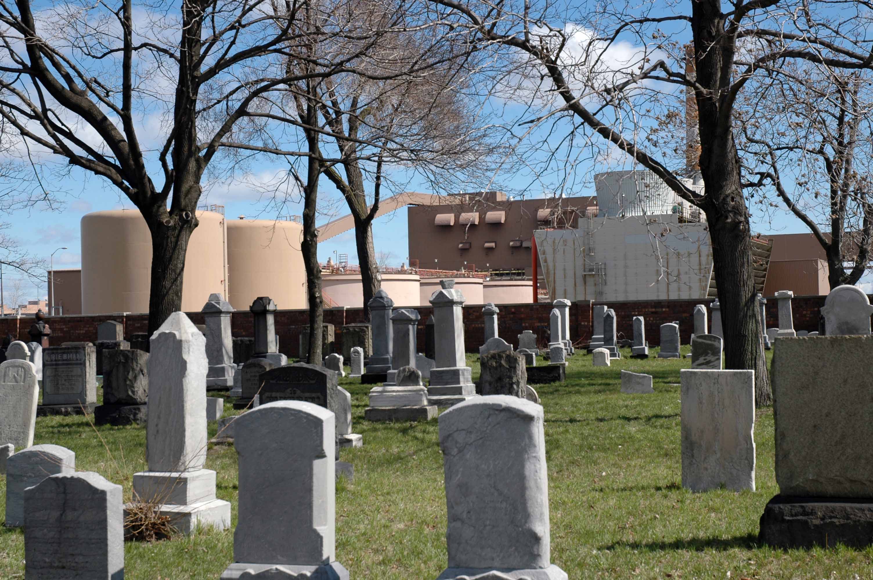
Figure 5. Beth Olem
cemetery.
Small white circles may be golf
balls. Cemetery maintenance crews
collect golf balls from the grounds that
executives apparently hit at
lunchtime into the cemetery from nearby
parking lots. Photo
courtesy of Chene Street History Study
archives.
The cemetery is no longer taking new
'residents.' In that regard,
it offers to researchers an advantage
similar to the opportunity
offered to foreign language students who
begin by studying Latin (or
another 'dead' language). There is no
(or little) change--the
'syntax' and
'grammar' of the situation are frozen.
These are true anchors for
process and a fine place to begin study,
prior to moving out, in this
case to the more dynamic setting of the
changing urban Chene Street
scene.
A First Step in Creating the Virtual Beth
Olem: The Walls
The
cemetery is a compact entity that is easy to
deal with
geometrically: it is a
rectangle. The walls around it
delineate it clearly and make it quickly
recognizable. In terms
of creating a virtual cemetery, the walls
serve as a good starting
point. Once the walled boundary is
created, then infill can
proceed with the walls as guides to reduce
placement error.
Accuracy in placement of the walls is
straightforward: it is easy
to read off the latitude and longitude from
a smartphone camera used to
take a photo next to the wall. General
placement is
straightforward from tracing the footprint
in Google Earth. What
is a challenge with modeling the walls is
getting the surface to look
correct so that the created visualization is
realistic.
Surface Pattern
It
is a simple matter to capture a swatch of
the pattern on the walls from
a photograph. However, it is not
possible to use that swatch,
only, to create the full wall--at least not
in a realistic
manner. In Figure 6a, a single swatch
of an arbitrary pattern is
used to tile a broad area; the visual effect
is not satisfactory.
One has a sense that the single tile might
be employed to greater
advantage; blue and orange pattern do not
align as the walls are tiled
(Figure 6b). The tiling of a plane
using geometric shapes is
called a tessellation (see Wikipedia
reference).

Figure
6a:
single pattern tile, based on a
background from MicroSoft PowerPoint.
|

Figure
6b.
Pattern of 8a used to tile walls.
|
To improve alignment and consequent
appearance and visual impression,
one might flip the single tile or rotate it
to create different
patterns and then align it with the base
tile of Figure 6a to create a
larger single tile to tile the walls
with. Figure 7 shows a flip
about a vertical axis in animated
fashion. Figure 8a shows the
flipped tile appended to the base tile;
Figures 8b, and 8c illustrate
the resulting pattern when 8a is applied to
the walls of a box.

Figure
7. Flip
of tile about a vertical axis.
In the case of the walls at Beth Olem, the
situation of Figure 8c
prevails; it is possible to find a swatch
from top to bottom.
Figure 9 shows the results of a model
created in Trimble
SketchUp. The edges along the tops of
the walls, as well as the
dots in the walls, align across the entire
wall. Look at the
grass stains on the bottom to see where the
vertical flip was
made. Figure 10 confronts the model
with the reality of a
photograph. There are no grass stains
on the outsides of the
walls. The reason there are grass
stains on the modeled walls is
that images from the interior side of the
walls were used as textures
on the outsides; use of actual images of the
exterior required
excessive removal of tree limbs not present
when the interior images
were used. Evidently,
there are varying degrees of wetness at
different times of the year. A similar
strategy of using a view
from the inside, and then flipping it, was
employed with the sign for
the cemetery, again so that it too might be
disentangled from the tree
limbs.
One might further refine the detail of
images; that action, however,
has nothing to do with establishing
process.

Figure 9. Beth Olem walls,
model.

Figure 10. Beth Olem Cemetery
entrance.
Photo courtesy of Chene Street History
Study archives.
In the situation above, a flipped tile was
appended to one side of a
base tile. Naturally, the flipped tile
might also be applied to
each of the other three sides to create
other tiling patterns.
The one selected to be exhibited is one that
works well for modeling
the Beth Olem walls. Thus, the first
step in wall completion is
solved. But, to learn more from this
'anchor' case, consider
other possibilities.
The Klein 4 Group: Pattern Alignment
Issues
The
case above employed a vertical flip of a
rectangular (non-square) base
tile to create a new larger tile by
appending the flipped tile to one
side of the base tile; it was an exercise in
'spatial mathematics'
(Arlinghaus and Kerski). What other
transformations of the base
tile might be employed to create other
larger tiles that improve tiling
alignment issues on a wall? Clearly,
one might flip the base tile
about a horizontal axis. Further, one
might rotate the base tile
through 180 degrees and still maintain tile
orientation. Figure
11a-d illustrates these possibilities.
Figure
11a. Base tile
|

Figure
11b. Vertical flip
|

Figure
11c. Horizontal flip
|

Figure
11d. 180 degree flip
|
Because the base tile is non-square,
rotation through 90 degrees will
not maintain tile orientation; the
'landscape' tile will rotate to a
'portrait' tile under such a
transformation. Are there, however,
other rigid motions (see Wikipedia
reference) of a non-square rectangle
that will yield new
pattern? Intuitively, the answer
appears to be 'no'. It is
possible to prove that answer using a
structure from a branch of
mathematics called group theory.
To introduce appropriate notation, replace
the visual pattern in the
non-square rectangles with numerical
pattern, labelling the vertices of
the rectangles as 1, 2, 3, 4. Thus the
sequence in Figure 13a-d
is replaced by the sequence in Figure 12a-d.

Figure
12a. Base tile
|

Figure
12b. Vertical flip
|

Figure
12c. Horizontal flip
|

Figure
12d. 180 degree flip
|
To
illustrate how to use the numbers,
represent the base tile as the
identity permutation on these four
numbers: (1)(2)(3)(4).
Represent the vertical flip as:
(12)(34), read perhaps as '1 goes
to 2' then once the end of a
parenthetical notational phrase is
reached, the last element 'goes' to the
first one, so here '2 goes to
1'. Similarly, represent the
horizontal flip as:
(14)(23). Finally, represent the
180 rotational flip as
(13)(24). Does this set of
permutations form a closed
system? If so, then there are no
other possible rigid motions to
use to generate larger tiles from the
base tile.
A 'group' is a mathematical structure
that may exist on a set of
elements with one operation. When
elements are combined using
that operation, the system is said to be
a group if it is closed (no
new elements are generated), if it is
associative (grouping using
parentheses is clear:
a(bc)=(ab)c), if there is an
identity
property: a*I = a, and if there is
a unique inverse for each
element: a*a(-1) =
I. In the case of the
permutations representing rigid motions
of a non-square rectangle I =
(1)(2)(3)(4). The operation, *,
involves combining permutations
as below.
(12)(34)*(13)(24)
is executed as starting on the left
(for example) with 1--in the first
permutation, 1 goes to 2; in the
second permutation, 2 goes to 4.
Thus, in the resulting product, 1 goes
to 4 or (14. Now, where
does 4 go? Start in the first
permutation--4 goes to 3 and in the
second permutation, 3 goes to 1.
Thus, in the resulting product,
4 goes to 1 so it is now correct to
close the parentheses (14).
Now go back to the first permutation
to see where 2 goes. In the
first permutation, 2 goes to 1; in the
second permutation, 1 goes to
3. So, in the result, 2 goes to
3: (23 . Then go back
to the first permutation where 3 goes
to 4 and then in the second
permutation 4 goes to 2. Thus, 3
goes to 2 and it is correct to
close the parentheses: (23).
Thus, (12)(34)*(13)(24) =
(14)(23). With a bit of practice,
one
can perform this operation
quickly. Look at a table composed
of
all possible permutation
'multiplications' (Figure 13). The
column on the left is the set of 'first'
permutations; the row across
the top is the set of 'second'
permutations
*
|
(1)(2)(3)(4)
|
(12)(34)
|
(14)(23)
|
(13)(24)
|
(1)(2)(3)(4)
|
(1)(2)(3)(4) |
(12)(34) |
(14)(23) |
(13)(24) |
(12)(34)
|
(12)(34) |
(1)(2)(3)(4) |
(13)(24) |
(14)(23) |
(14)(23)
|
(14)(23) |
(13)(24) |
(1)(2)(3)(4) |
(12)(34) |
(13)(24)
|
(13)(24) |
(14)(23) |
(12)(34) |
(1)(2)(3)(4) |
Figure
13. Group table, Klein 4 Group.
Verify
that no new elements were
created: all are displayed in
the
table. Verify that the
associative law holds: for
example,
(12)(34)*[(13)(24)*(14)(23)] is the
same as
[(12)(34)*(13)(24)]*(14)(23).
Show for each grouping; begin by
working from within sets of
parenthetically enclosed
permutations. It is
straightforward from the table that
(1)(2)(3)(4) is an identity element;
it is also straightforward from
the table that there is no other
identity element. Finally, read
the table to see that each element is
its own inverse:
(12)(34)*(12)(34) = (1)(2)(3)(4), for
example. Thus,
this set of four permutations,
representing rigid motions of a
non-square rectangle, forms a
group. It was discovered by
Felix
Klein and is referred to as the Klein
4-Group (Vierergruppe) and
is often denoted V.
Thus, because the group structure is
verified, there are no other
patterns of the sort above, based on a
non-square rectangle, that can
be used to generate wall tiling.
Of course, one can improve
pattern alignment by using a larger
tile, such as the one in Figure 8a,
and flipping that to create an even
larger base tile.
Figures 14a-c suggest one such
strategy: apply a vertical flip
to
the base tile, append that to the base
tile (Figure 14a) then apply a
horizontal flip to the tile in 14a to
create a larger tile in Figure
14b. This new tile, as shown in
Figure 14c, will combine both the
good side-to-side alignment and
top-to-bottom alignment of the
vertical
and horizontal flips. The tile
is new, the alignment pattern of
wall tiling is new and improved;
however, there is no new motion
involved, as the Klein 4 Group shows.

Figure
14a.
Vertical flip of base tile
appended to base tile
|

Figure
14b.
Horizontal flip of 14a appended
to 14a
|

Figure
14c.
Argyle style of pattern
|
Here,
only a simple non-square rectangular
tile was considered. One
might
carve out pieces of a rectangular tile
and glue them on top or bottom
or sides and create oddly-shaped
Escher-like fish that fit together
perfectly in two different directions
and at different scales.
The process is similar and employs the
same general style of
reasoning. One may use the chain
of reasoning for non-Euclidean
as
well as Euclidean objects (see comments
in the Escher Wikipedia
reference involving the Escher 'Circle
Limit series). The
subjects of group theory and of
tiling are deep ones--group theory lies
at the theoretical root not
only of simple tiling such as that shown
here but also at that root of
any tiling (see for example, Wikipedia,
'Wallpaper group').
References for further reading are
suggested at the
end of this document.
References
Cited
- Archive,
Chene Street History Study, The
University of Michigan, Ann Arbor.
- Arlinghaus,
Sandra L. and Kerski,
Joseph. 2013. Spatial
Mathematics:
Theory and Practice through
Mapping.
Boca
Raton: CRC Press.
- Arlinghaus,
S., Haug, R., and Larimore, A.
Nov. 2011. GEOMAT Guide:
Directions for
Building a GEOMAT Web Architecture
for any Investigation or Case
Study. http//:www.geomats.org/
- Krzyzowski,
Marian. Director, Chene Street
History Study; Director, Institute
for Research on Labor, Employment,
and the Economy, The University of
Michigan, Ann Arbor.
Software
Used
Adobe
PhotoShop
Google
Earth
MicroSoft
Office, PowerPoint, Word.
Trimble
SketchUp
References
for further reading
Birkhoff,
G. and Mac Lane, S. 1961. A
Survey of Modern Algebra.
New York: MacMillan.
Coxeter, H. S. M., 1961, Introduction
to
Geometry. New York:
MacMillan.
Coxeter, H. S. M., Emmer, M., Penrose,
R., and Teuber, M. L.
eds. 1986. M. C.
Escher:
Art and Science.
Amsterdam: North-Holland.
Grünbaum,
Branko and Shephard, G. C.
1987. Tilings and Patterns.
New
York: Freeman.
Herstein,
I. N. 1975. Topics in
Algebra, New York: Wiley.
Loeb, Arthur. 1976. Space
Structures: Their Harmony and
Counterpoint. Reading,
MA: Addison-Wesley.
Schattschneider,
Doris
(June/July 2010). "The
Mathematical
Side of M. C. Escher"
(PDF). Notices of the
American Mathematical Society
(USA) 57
(6): 706–18.
Weyl, Hermann. 1952. Symmetry.
Princeton:
Princeton University Press.
Wikipedia:
|
|