Ann Arbor,
Michigan:
Virtual Downtown Experiments, Part II
Sandra Lach Arlinghaus
Adjunct Professor, The
University of Michigan
School of Natural Resources and Environment; Taubman
College of Architecture and Urban Planning.
Member and Secretary, Board of Trustees, Community
Systems Foundation (International NGO)
Member, Secretary, Vice-Chair, and Chair, City Planning
Commission,* City of Ann Arbor
(1995-2003);
member, Ordinance Revisions Committee (1995-2003),
Master
Planning Committee (2002-2003), and Environmental Commission
(2001-2003),
City of Ann Arbor.
For background information, please view
this
link to Part I: Ann
Arbor, Michigan: Virtual Downtown Experiments
Material in this article is part of a forthcoming book
by the author and William C. Arlinghaus entitled Spatial
Synthesis
(in
press).
Thanks to:
Merle Johnson of the City of Ann Arbor for
permission to
use City of Ann Arbor base maps and aerials in this article.
Karen Hart, Planning Director, and Chandra
Hurd, Planning
Department, City of Ann Arbor, for files concerning building height in
the downtown.
Matthew Naud, Environmental Services
Coordinator and Emergency
Services Coordinator, City of Ann Arbor.
Prof. Peter Beier, Director 3D Laboratory,
Media Union, The
University of Michigan and his staff members Lars Schumann and Brett
Lyons.
Brief Background
Ann Arbor is a small city (of just over 100,000 population) in
southeastern
Michigan. It is home to the main campus of The University of
Michigan,
a state university with over 35,000 students on the Ann Arbor
campus.
The student population composes about 1/3 of the population of the
city.
Much of the rest of the population works at the university in some
capacity
or in research industry, businesses, government, or institutions that
locate
near the campus. Most cities in the US have shapes that are
topologically
equivalent to a circle, in terms of paying taxes to the city:
land
parcels that lie within the city boundaries pays taxes to the
city.
There are, of course, cities that contain enclaves within their
boundaries
that are not part of the city itself. In the case of Ann Arbor,
however,
and other small cities that contain large state universities, the city
is more of an annulus (doughnut) in shape. A large hole,
containing
the university is cut out of the city: lands in this hole do not
pay taxes to the city. Hence, a disproportionately large property
tax burden is placed on owners of non university parcels within the
city
(although of course the presence of the university is vital to the
well-being
of the city in numerous ways). Ann Arbor is a college town.
Thus, there is a need to have mechanisms to create continuing
economic
development within the city. One way is to increase the stock of
housing and space for commercial and other establishments in support of
that housing. This path is all the more attractive in light of
enduring
interests in reducing "sprawl" and in preserving open space in the more
rural surrounding lands. In a city with few remaining empty
buildable
lots, this approach seems to offer few alternatives, the most obvious
of
which is to increase the density of dwelling units within the
city.
When density increases are proposed in established residential
neighborhoods
there is often loud and long public objection from residents of those
neighborhoods.
There may also be serious environmental considerations, as well.
Few residents, however, seem to object to increasing density in the
downtown:
many who already live in the downtown moved there with an acceptance of
taller buildings. Residents of the city who do not live in the downtown
often seem not to care about the idea of increasing density in the
downtown.
What people do seem to care about, however, is what an increase in
downtown
residential density may mean to the character, appearance, and feeling
of the downtown: to its skyline and to the pedestrian
experience.
To some, an 18 story building is a visual blight on the skyline that
provokes
negative comment every time it is viewed; yet, others note that they
have
become accustomed to it and view it as an old, familiar friend.
Building
height can be a source of substantial dispute.
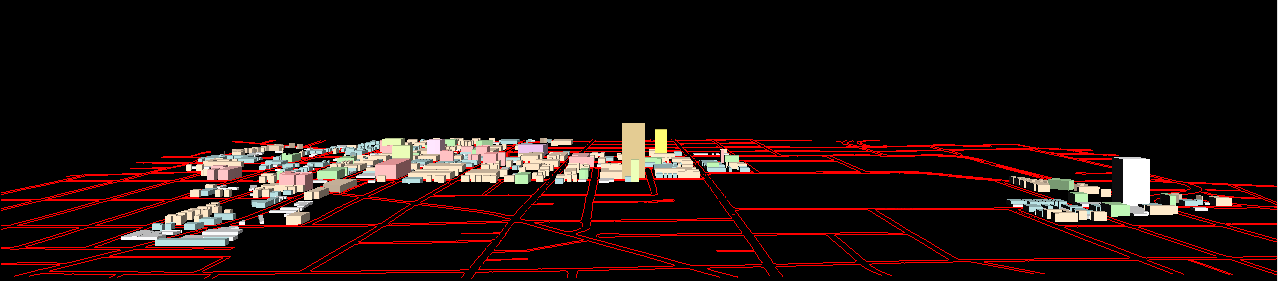
Inventory of the Vertical City
Prior to considering new tall buildings, it seems appropriate to create
an inventory of existing buildings in the downtown area. (In Ann
Arbor, the "downtown" generally refers to the "Downtown Development
Authority"
or DDA: a state-enabled authority that can capture increases in
taxable
value to pay for improvements within the defined boundaries.) To
create this inventory, building footprints were digitized from high
quality
aerial flown in 2002. Heights were assigned to buildings based on
information from the City of Ann Arbor Planning Department (only
partially
complete). When the building footprints are sorted out according
to height it becomes possible to visualize how the taller buildings are
arranged with respect to the shorter buildings. Figure 1 shows an
animation of this pattern. In that animation the reader has an
opportunity
to study different layers of downtown space in relation to a plain
backdrop
and finally to an aerial of the city.
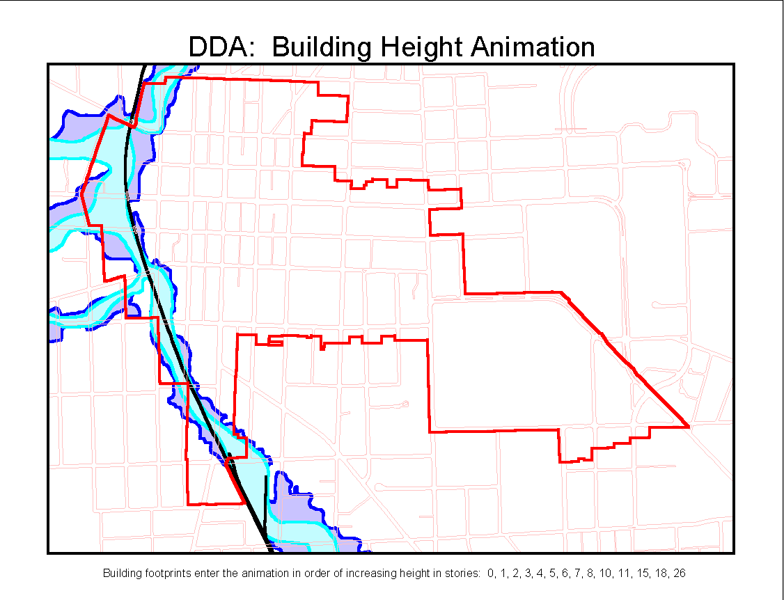
Figure 1. Animation of
existing
building height in downtown Ann Arbor, Michigan. |
The evidence of Figure 1 suggests that buildings of 1, 2, and 3
stories
are common in the downtown. Indeed, casual conversations with
individuals
from around town suggest that no one objects to buildings of any of
these
heights. One might wonder if that is because they somehow fit a
sense
of Ann Arbor well or if that is because they are prevalent and people
become
accustomed to them. In any event, one might imagine an ordinance
which allows three stories "by right" on any downtown parcel. The
question then becomes, how high elsewhere on prime parcels? For
this
question one might look to the spacing pattern of existing buildings
taller
than three stories. Tall buildings adjacent to other tall
buildings
can create wind tunnels and block wide channels of light. Tall
buildings
built lot line to lot line may present those as well as other unwelcome
effects.
The Floor/Area Ratio as an Urban Planning Tool
The problem of where to locate tall buildings, with sensitivity to
existing
building types on adjacent and nearby lots, is a difficult one.
In
Ann Arbor, building height is currently limited by "floor area ratio"
(FAR).
The FAR is calculated as the ratio of floor area in a building divided
by parcel area, times 100. If a given parcel has an FAR of 100
assigned
to it, then a building footprint built lot line to lot line may have a
height of 1 story. If a parcel has an FAR of 200 assigned to it,
then a building footprint built lot line to lot line may have a height
of 2 stories. Similarly, an FAR of 300, assigned to a parcel,
yields
a building of height 3 stories covering the entire parcel.
Thus, on a parcel with an FAR of 300, one might, instead, build a
building
on half of the lot area but of height six stories, or on a third of the
lot area but of height 9 stories. On the same parcel, a 30 story
building could be built only if its footprint covered one tenth of the
land area of the parcel.
The FAR provides a height limit based on the size of foundation
needed
to support a tall building. It also offers subtle encouragement
for
preserving some amount of open space and visual variation in the region
to which it applies. The drawback is that a tall building may get
built with no regard to the broader context of how that new building
will
fit in with existing buildings on the surrounding parcels. A
possible
side effect of using FAR (alone) to limit height is that it might
encourage
parcel amalgamation by large developers, thereby driving out desired
local
small business owners. [Note: in Ann Arbor, there are also
"premiums" designed to encourage residential construction, and other
uses
viewed as "desirable" in the downtown; these allow an increase in
FAR.
They will not be covered in this discussion as they introduce no new
theoretical
issues--just complexity of detail.]
The Floor/Area Ratio, a Closer Look: The Hyperbola as an
Urban
Planning Tool
In a recent article Claudia
Iturriaga
and Anna Lubiw consider the problem of labeling maps. Because the
current mapping environment is one that allows dynamic positioning of
maps
(zooming-in and panning), they consider the problem of non overlapping
placement of text boxes to be one that is sufficient to solve with text
boxes only at the perimeter of the map (with map content in the
interior).
They note that if the aspect ratio of the label (ratio of height to
width)
is permitted to vary, with label area held constant, then labels can be
fit together in a variety of patterns that will permit a balanced
display
of map and text boxes. The requirement of constant label area
ensures
that a certain amount of text content is communicated; shape is
permitted
to vary. Thus, if the label is viewed as having a fixed lower
left
corner, then the upper right corner varies along the track of the first
quadrant of a rectangular hyperbola with origin at the lower left
corner.
That is, if width is measured along the x-axis and height is
measured
along the y-axis, and the area of a label is fixed at K,
then the equation describing the label is xy =
K. This
latter equation is precisely the equation of a rectangular hyperbola in
the first and third quadrants intersecting the line y = x
at (K, K).
It is not a long conceptual leap to imagine the rectangular areas
arranged
around the perimeter of a rectangular map as being similar to the
rectangular
areas of building footprints arranged around a rectangular block of a
downtown
based on a gridded street system. The idea of a rectangle with an
elastic aspect ratio tracing out the path of an hyperbola is similar to
the idea of Floor Area Ratio (FAR) discussed above. From an
abstract
viewpoint, the FAR/100, or number of stories, times the parcel area
serves
as an envelope within which buildings may be built. For example,
if a parcel has area 100,000 square feet and an FAR of 300, then
300,000
square feet of floor area may be built on the parcel: as a 3
story
building lot line to lot line front, back, and sideways (green building
in Figure 2); or, as a 6 story building with each floor having 50,000
square
feet on half the parcel (yellow building in Figure 2); or as a 12 story
building with each floor having 25,000 square feet on 25% of the parcel
area (magenta building in Figure 2). What is constant is the
value,
K
=
(FAR/100)*(parcel area). If one graphs this function, with parcel
area on the horizontal axis and FAR/100 on the vertical axis, the
result
is a rectangular hyperbola, xy = 300,000 (Figure 2).
Different
masses of building in relation to land area result depending on the
height
one chooses.
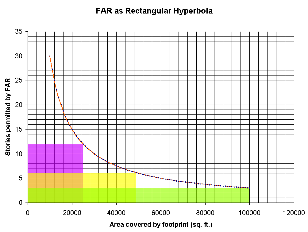
Figure 2. Rectangle with
elastic
aspect ratio and lower left corner fixed at the origin traces out part
of one limb of a rectangular hyperbola xy = 300,000. |
When one abstracts away from the grid suggested by Figure 2, and
focuses
instead on the hyperbola, it is possible to extend the analysis to the
more global scene of the entire DDA and to the issue of building mass
in
relation to land area. Thus, consider that the x-axis
units
are now percent area in the downtown; then, the right-hand limit of the
hyperbola is 100% of the land in the DDA. Under these
assumptions,
what the hyperbola of Figure 2 now says is that 100% of the DDA may be
covered with 3 story buildings: that a 3 story building may be
constructed,
by right, anywhere within the DDA. It also says that 50% of the
land
area in the DDA may be covered with 6 story buildings, or that one
quarter
of the land area in the DDA may be covered with 12 story buildings, or
that 10 percent of the land in the DDA may be covered with 30 story
buildings.
The use of the FAR to govern building height may play our at a regional
(DDA) level as well as at a local level of the individual parcel.
The hyperbola captures the FAR in a systematic manner and it does so at
all scales, from local, to regional, to global. It does not
reflect
planning and geographic elements that the FAR does not capture such as
(but not limited to) heights of neighboring buildings and other
adjacency
considerations, historic preservation issues, shadow or wind tunnel
effects
and other quality of life issues, or lateral or upper story setback
concerns.
Issues such as these require the human elements of judgment and common
sense. The mathematical implementation can do much, but not all;
it is a tool of humans, not a replacement for human thought (although
numerous
abstract connections remain to be probed: from cartography, to
urban
planning, to the Zipf rank-size rule and the lectures
given by Michael Batty at The University of Michigan and Eastern
Michigan
University in the spring of 2003).
The principles set forth here, would enable one to consider the
total
mass of building square footage permitted according to FAR, independent
of municipality and local concerns. Subtracting the actual built
up area from that would give an estimate of the remaining mass that
could
be built, by right, according to code. Within that remainder, one
might calculate how many more 3 story buildings could be built; how
many
more 6 story buildings; how many 12 story buildings (or whatever height
in whatever units). Such a strategy can completely characterize
the
mass of building in relation to land area and may suggest a basis for
the
control of that mass, especially when one decides what future is
desired
and works back from that to create ordinances and code that will lead
to
that desired outcome (an approach similar to that take by others, as
for
example
by people at ChicagoMetropolis2020).
It offers, however, no guidance as to where tall buildings might be
placed
in relation to each other or in relation to existing structures, as to
which parcels might contain tall buildings, as to wind, light, and
sound
issues, and as to a host of other qualitative issues. Other
approaches
might involve a guide to the spacing of buildings (forthcoming),
buffers
around existing buildings as zones of limited height, or legislated
design
standards. It is for creative needs such as these, to be
superimposed
on measures of sheer mass or quantity that can be captured generally as
mathematical and geographical propositions, that cities require the
service
of professional planners and a host of municipal authorities and
support
personnel.
Beyond the Floor/Area Ratio: Virtual Reality as an Urban
Planning
Tool.
Virtual reality, the envisioning of
alternative
three-dimensional scenarios on a computer screen, offers to decision
makers
the capability to see how the massing of buildings and the general
design
of the urban landscape might look with various changes. In the
case
of Ann Arbor, that might mean envisioning the downtown with new tall
buildings
in a three-dimensional model that can be viewed at the pedestrian
level:
as a virtual landscape that can be navigated on the computer screen by
City Council members as they sit with laptops in Council Chambers or by
members of the public as they sit at home or in public libraries using
computers with internet connections. Part I
of this topic showed virtual reality of the downtown based on
-
VR
1: parcels were extruded to form chunky buildings that
filled
entire parcels, lot lines to lot lines, with height assigned by FAR and
zoning ordinance (C1A, 200% FAR; C1A/R, 300% FAR; C2A, 400% FAR; C2A/R,
300% FAR; C2B/R, 300% FAR).
-
VR
2: parcels were extruded to form chunky buildings that
filled
entire parcels, lot lines to lot lines, with height assigned by records
from the Planning Department of the City of Ann Arbor.
Additional work has yielded refinements on these files. Building
footprints were digitized from an aerial of the downtown, flown for the
City of Ann Arbor in 2002. Many of the footprints had heights
from
the records of the Planning Department. However, a number (over
300)
did not. Buildings with no height were assigned the height based
on FAR by zoning type (using information from the City
of Ann Arbor Zoning Ordinance) calculated in association with the
virtual
reality in Part I, above.
The following sequence of interactive maps, made using the
ImageMapper
3.3 extension to ArcView, shows the results, using maps and aerials in
various combinations:
-
I-Map
1: Click here for a link to an interactive map showing
building
footprints and height (on mouse-over) as well as building address and
street
names (on mouse-over). Parcel boundaries are shown on the
underlying
aerial and on the green Downtown Development Authority (DDA)
area.
The Allen Creek floodway (underground) and flood plain are shown,
shaded,
respectively in blue and turquoise. Click on a building or a
street
to see associated entries in the underlying database.
-
I-Map
2: Click here for a link to an interactive aerial showing
parcel boundaries, zoning, building height (on mouse-over), and street
name. DDA outline, only, is shown in light yellow so the user may
zoom in to get a closer view of the aerial within the DDA (up to 800%
enlargement--can
see cars clearly). The Allen Creek floodway (underground) and
flood
plain are shown, outlined, respectively in blue and light blue; again,
because the shading is removed, the viewer may look at the content of
the
floodway/floodplain in greater detail than above. Click on a building
or
a street to see associated entries in the underlying database.
-
I-Map
3: Click here for a link to an interactive aerial showing
zoning boundaries in the downtown, zoning type (on mouse-over),
building
height (in the "zoneht" record of the database), and street name.
Click on a building or a street to see associated entries in the
underlying
database.
This strategy necessarily produces error. Buildings that do not
occupy
a full parcel may well be taller than indicated here (as the FAR
permits
them to be). Others may be lower than what is allowed by FAR
because
they were not developed to the maximum permitted. Still others
may
be yet another height because they were part of a Planned Unit
Development
(PUD). (PUD designation is a custom zoning that permits projects to be
built outside the standard zoning currently present for that parcel
when
there are good reasons to consider such action and when there is
substantial
public benefit, defined in City Code, for such action.) Finally,
some parcels may not be developed for buildings: they may house
parking
lots or other non-building uses. Obviously, parcels that are
empty,
parcels housing parking lots, or parcels containing buildings of height
less than permitted by FAR are targets for development or
re-development.
One block often targeted in this manner is the "Brown Block": the
block of land bounded by Ashley, Huron, First, and Washington Streets
(Figure
2). Vacant lands are easy to select from an aerial; what is
not easy to see from an aerial is how new buildings might appear on
them
in relation to existing buildings. For that visualization, virtual
reality
is critical to gaining either a pedestrian's eye, or a bird's eye,
view.
On November 9, 2003, City Council Member Jean Carlberg (and Mayor
ProTempore,
Planning Commissioner, and member of the Ordinance Revisions
Committee),
City Council Member Joan Lowenstein, City of Ann Arbor Planning
Director
Karen Hart, and former City Attorney (on two occasions) Jerold Lax,
visited
the GeoWall (with the author and others, a total of 14) at The
University
of Michigan's 3D Laboratory at the Media Union (Dr. Peter Beier,
Director).
At that time, they had the opportunity to view the files above at a
scale
that permitted them to feel as if they were walking among the
buildings.
Each was given the map displayed in Figure 3 and an earlier version of
the commentary following the map. The red building on the map in
Figure 3, at the southeast corner of Fifth and Huron Streets, is a
location
mentioned as a possible site for a new tall building by Ann Arbor Mayor
John Hieftje (in personal communication with the author and
elsewhere).
The commentary following the map enumerates the steps taken to build a
virtual structural base of the downtown to use as a model to consider
density/height
issues in the downtown.
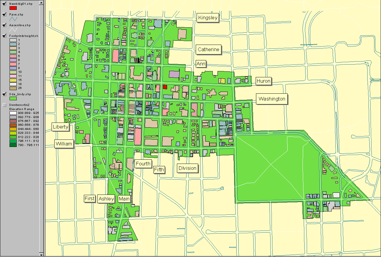
Figure 3. Map handed out to
participants
in the GeoWall display of November 9, 2003 at the Media Union of The
University
of Michigan. |
Procedure used to date to create a structural building
base of
downtown (no detail):
-
Building footprints were digitized using a city aerial (.tif
file).
They are represented in the map above as polygons filled with color
according
to building height (all buildings of the same height have the same
color).
-
Issues with height:
-
Over 300 polygons had a value of "0" height. For all but 32 of
those
polygons, the digitized building footprints were assigned values based
on the FAR for the zoning category. Because the parcel outline
generally
exceeded the building footprint in area, this decision likely produces
buildings that are shorter than what is permitted (although of course
there
may be actual buildings that have been constructed at less than what is
permitted by right).
-
For the remaining 32 polygons, for which there was no data, a height of
3 stories was inserted (in later files, one was adjusted to 7 stories
based
on field evidence (Ashley Mews)).
-
Stories were assumed to be 12.5 feet in height.
-
Contours, with a contour interval of 5 feet, were used to create a
triangulated
irregular network as a topographic base level from which to
measure
building height (rather than from a flat geometric base level).
-
VR
3: topographic base level in 3D
-
VR
4: topographic base level with buildings extruded from
that
level. This file may take a long time to load and it may be
difficult
to navigate because of the extended load time.
-
Actual height Virtual Reality:
digitized building
footprints are superimposed on parcels in the downtown core zones.
-
These VR experiments depict the
downtown using actual
building heights, where known that are extruded from a topographic
base.
This base is a Triangulated Irregular Network (TIN) made from a City of
Ann Arbor contour map with a contour interval of 5 feet. There
are
three sets of files for June 21:
-
VR
5: sun in the southeast (morning),
-
VR
6: in the south (noon),
-
VR
7: and in the southwest
(afternoon).
This was done in order to suggest variation in lighting conditions with
season and with time of day. The lighting scheme is designed for hill
shading
and is therefore really only useful for suggesting shadow location as
it
does not account for light reflected from impervious surface.
- Later experiments involved inserting building heights for
the 300+ parcels
of unknown height, as above. Links to
-
VR
8: a low sun scene (sun in the southwest) with the new
building
and
-
VR
9: a high sun scene (sun in the southwest) with the new
building
are included here. In these scenes parcels are extruded from
topographic
base level although it is not shown directly as a TIN in the scenes (in
the interests of reducing file load time and map clutter).
-
A new building was added in response to comments from Mayor John
Hieftje
and is shown as a red block in Figure 3 and also in the attached
aerial..
-
Earlier versions of files were shown to the Ordinance Revisions
Committee
of City of Ann Arbor Planning Commission.
-
Karen Hart and Matthew Naud, both of the City of Ann Arbor, previewed
earlier
files in the immersion CAVE and on the GeoWall at the 3D Laboratory
(Peter
Beier, Director) of the Media Union of The University of Michigan.
-
Hart noted the utility of this tool for urban planning and mentioned
one
local project in particular; she agreed with the author that this tool
might be useful in the context of a maximum height ordinance in the
downtown;
-
Naud noted the utility of this tool for emergency management, including
as a training tool for first responders. He expressed a desire to
have building textures and other detail that would aid in building
recognition
introduced into scenes. Naud also suggested that knowing where
hazardous
materials were located would be useful to first responders. He
followed
up by suggesting a connection to others and helping to arrange, and
participating
in, meetings with them. These meetings have led to some proposals
to fund emergency management activities linking various groups of
individuals
from the public and private sectors
-
Beier noted, on viewing the earliest files in the CAVE, that the
buildings
appeared to be too tall as one took a walk through the virtual
downtown.
Later, Lars Schumann (Programmer Analyst II and Lab Manager) and Brett
Lyons (Programmer Analyst I), of the 3D Laboratory, Media Union, told
the
author that the .vrml files used in the CAVE and on the GeoWall have
units
in meters. Taejung Kwon (Ph.D. student, Taubman College of
Architecture
and Urban Planning and student in Engineering 477) noted (later yet)
that
one might calculate a z-factor to convert feet (used as the
default
unit in ArcView in City of Ann Arbor maps) to meters used in .vrml
files.
Other students in the group, Paul Oppenheim, Adrien Lazzaro, and Aaron
Rosenblum agreed with Kwon.
|
Current activities:
-
Research continues on building a "3D Atlas of Ann Arbor" designed to
aid
decision makers in a variety of contexts from Planning to Emergency
Management.
It will also serve as a pilot project for a number of more global 3D
atlases.
-
The author together with Matthew Naud and John D. Nystuen
(Professor
Emeritus, College of Architecture and Urban Planning, The University of
Michigan) are serving as faculty advisors in Professor Peter Beier's
Engineering
477 (College of Engineering, The University of Michigan) course on
virtual
reality, Fall 2003. They are working with the team of four
students
mentioned above. The students
have created a localized study for the "3D Atlas of Ann Arbor" at the
intersection
of Liberty and Main Streets. It will serve as a pilot study for
other
detailed 3D urban views.
|
Comments from the meeting from November 9, 2003
and
subsequent follow-up:
-
Council Member Carlberg noted that she might also wish to
know more
about where the shadows of new buildings might fall. Lighting
changes
are difficult to model in VR; however, with aerials that show existing
building shadows, it is not hard to imagine where shadows of new
buildings
might fall. Thus, in the
linked
aerial
one sees a red square on a parking lot corresponding to the
location mentioned as a possible location for a tall building by Mayor
Hieftje. The buildings around it cast shadows that extend almost
across the street. A new building on the red square, of height
greater
than adjacent buildings would cast a shadow on both sides of the
street.
Shadow position is important when considering budgetary allocations
from
the city's street tree escrow. It is also important in creating a
positive pedestrian experience in the downtown.
-
Council Member Lowenstein commented to the author that the
files
above were, with navigation aids added, probably enough to be quite
useful
to City Council. Both she and Planning Director Hart noted their
utility in considering issues involving height in the downtown as they
relate to a recent city initiative to increase the residential
population
in the downtown. She also noted that the addition of callouts
(notes)
that show which buildings might contain hazardous materials, or similar
information, might be helpful to firefighters and other emergency first
responders. Two-dimensional interactive maps or aerials may well
be sufficient for a hazardous materials inventory.
-
An I-Map based on an aerial might offer one approach. On the
linked
map
the mouse-over callouts shows the building address for
three
locations. Click on a location to reveal elements of the database
associated with each site. In seeing all buildings simultaneously
one gets an immediate picture of adjacency patterns: for example, a
fire
in one building may need immediate containment on the eastern edge to
prevent
spread to an adjacent building on the east containing volatile
material.
Careful database construction is critical: the mapping, in this
case,
is easy in relation to the database construction.
-
A very simple approach might simply employ Adobe Photoshop (version 7.0
was used here) to work with a high quality aerial photograph of the
City.
In the
attached
aerial
note files and voice files have been added to City Hall, to 219 S.
Main, and to the central quadrangle (the "Diag") of The University of
Michigan.
Thus, emergency workers might have not only the benefit of reading
notes
attached to buildings that specify the locations of hazardous
materials,
but also the capability to hear voice transmissions of such locations
when
already in a tight spot. The drawback to this style of approach
is
that it requires the user to download the file and open it in Adobe
Photoshop
(or use some similar strategy to read the notes). If, however,
the
emergency management team already has Photoshop loaded on laptops, this
is not much of a disadvantage. Indeed, it might be viewed as an
advantage
in file security given that it does not play directly on the Internet.
-
Planning Director Hart, noted in addition, the importance of
modeling
upper story setbacks as a next step. She also suggested possible
specific locations in the downtown where VR might be particularly
helpful,
including in the modeling of various aspects of long-standing plans for
a renovation of governmental space. As convincing and as helpful
as virtual reality can be, it is however, only virtual. When one
walks away, it remains only in the mind. Another exciting
technological
tool that the group saw is the 3D "printer" that creates true 3D
objects
representing the experienced virtual reality. Hart also noted
that
she could see numerous uses for this tool. Indeed, sometimes the
end desired suggests the process to get there, not only in master
planning
and other forms of planning, but also in the tools used in planning.
The display below presents the final experiments in this set (given
to Ann Arbor City Council in December of 2003) as the first in a series
of possible 3D mapping tools to aid in making a variety of
difficult
decisions: for Ann Arbor as well as more globally. It
includes
parcels extruded from building footprints, with the sun set in the
south
at a "low" setting, using an invisible topographic base created from a
TIN made from a topographic map with a contour interval of 5
feet.
Buildings have been adjusted using a z-factor of 0.3048.
It
also includes street labels that appear as one moves around at a local
level as well as navigation aids (click in the lower left corner of
Cosmo
Player) of assigned camera viewpoints. These, coupled with using
the "driving" capability of Cosmo Player, help in getting around the
virtual
downtown so that one does not get lost in the space of virtual Ann
Arbor!
VR
10: this virtual model of downtown
Ann Arbor
shows views of the downtown
-
from the south, along a
corridor between
Division and State streets
-
from the south, looking
north along
the Main Street corridor
-
from the east, looking
west along the
Huron Street corridor, at pedestrian level.
Use the list of viewpoints
in the lower
left-hand corner to be taken to these three different camera
positions.
Also, use the tools in Cosmo Player to structure your own route through
the downtown at a bird's eye or human's eye level.
Labels on the streets
will appear
as one zooms in. Some graphic tasks that are easily accomplished
in a GIS are not so easily accomplished in virtual reality. The
lettering
for these labels was made in a polygon layer of ArcView by tracing
default
lettering. Automatic labels that are easy to produce in a 2D map
do not reproduce in the 3D version. Thus, as with the building
footprints,
digitizing letters will make them appear. In the process of
digitizing
letters such as "B" or "D," one might be reminded of converting a
multiply
connected domain to a simply connected domain and consequently the
Jordan
Curve Theorem from topology or the Cauchy-Goursat Theorem (or others)
from
the theory of functions of a complex variable.
It is remarkable to see that strong interdisciplinary connections
between
geography and geometry arise even in the most mundane of mapping tasks.
|
-
VR
11.1, 3 story building added at southeast
corner
of Huron and Fifth
-
VR
11.2, 4 story building added at southeast
corner
of Huron and Fifth
-
VR
11.3, 5 story building added at southeast
corner
of Huron and Fifth
-
VR
11.4, 6 story building added at southeast
corner
of Huron and Fifth
-
VR
11.5, 7 story building added at southeast
corner
of Huron and Fifth
-
VR
11.6, 8 story building added at southeast
corner
of Huron and Fifth
-
VR
11.7, 9 story building added at southeast
corner
of Huron and Fifth
-
VR
11.8, 10 story building added at southeast
corner
of Huron and Fifth
-
VR
11.9, 11 story building added at southeast
corner
of Huron and Fifth
-
VR
11.10, 12 story building added at southeast
corner
of Huron and Fifth
This set of files shows a
sequence
of views, all with the same two camera angles--the first is a view of
the
entire downtown and the second is a view looking west along Huron
Street,
from a vantage point to the east of State Street. Use the navigation
system
in the lower left-hand corner to see the views from these preset camera
positions; they offer a standard source for comparison as one switches
from model to model that the free-roaming form of navigation does not.
The red building in each model is a virtual building built on the
southeast
corner of Huron and Fifth, across from City Hall. It is the empty
spot selected by Mayor Hieftje on a number of occasions as one location
to consider for building a tall building. The sequence of files
shows
the virtual building with different numbers of stories: 3, 4, 5,
6, 7, 8, 9, 10, 11, and 12. The general view of the downtown
suggests
how the new building might or might not fit in the overall skyline
view.
The local view along Huron Street suggests what the pedestrian
experience
might be. |
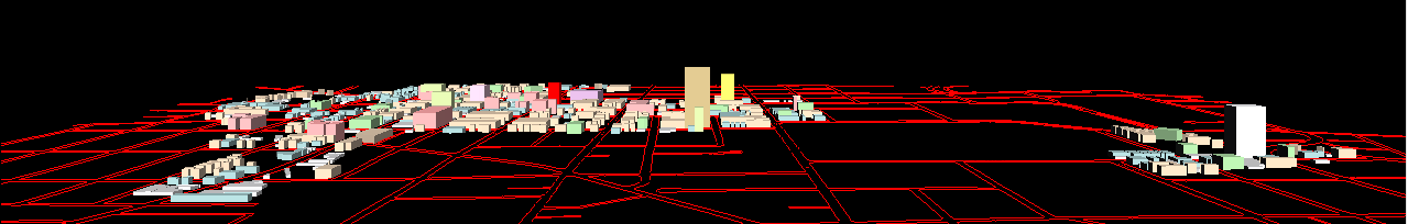
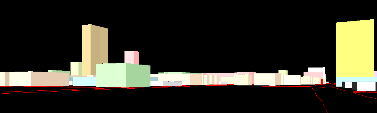
Figures 4a and 4b below show animated
sequences of
screen shots from the virtual reality files. Thus,
-
in Figure 4a, one can watch the bright red
building "grow"
from 3 to 12 stories, in 1 story increments, in the center of the DDA,
across the street from City Hall, at the southeast corner of Huron and
Fifth streets. A view such as this one suggest the impact the new
building might have on the overall skyline. To get a good general
picture, one might wish to have such animations from more than one
vantage
point and for change involving more than one building. This
animation
suggests a style of analysis at the global level of the entire downtown.
-
in Figure 4b, one can watch the same
building grow (as
in Figure 4a, again in 1 story increments) but from a far more local
viewpoint
and from a level closer to a pedestrian's eye view. A sequence of
such animations might be helpful in understanding the impact of new
structures
on the pedestrian experience.
|
Next steps include:
-
Field checking of building heights
-
Modeling of upper story set backs
Possible future activities
-
Thinning of file size based on scale.
-
Produce a number of other files based on various lighting possibilities.
-
Introduce cars along the streets, pedestrians on the sidewalks, and so
forth.
-
Model the weather (colleague John D. Nystuen suggested modeling a snow
storm). Nystuen also suggested modeling the underground
infrastructure.
-
Consider how practical, day to day elements of decision making might be
aided.
-
Might VR files serve to replace the model consideration in the PUD
zoning?
-
If so, what sort of ordinance revision would be necessary and what
legal
ramifications might there be in such a consideration or in related ones?
More generally, what are the legal questions involved in using VR as
a planning and emergency management tool; do they differ from those
associated
with using 2D analysis for such purposes?
*The author acknowledges productive meetings with and
assistance
from
-
her colleagues on the City of Ann Arbor Planning
Commission
(Sandra Arlinghaus (Chair), Kevin McDonald (Vice-Chair), Scott Wade
(Secretary),
Braxton Blake, Jean Carlberg, Kristen Gibbs, Christopher Graham,
William
Hanson, and Steve Thorp);
-
the Ordinance Revisions Committee of that
Commission (Hanson,
Chair; Carlberg, Arlinghaus, Blake);
-
the City of Ann Arbor Planning Department staff
(Karen Hart,
Planning Director; Wendy Rampson, Coy Vaughn, Donna Johnson, Jeff
Kahan,
Chandra Hurd, Alexis Marcarello, Christopher Cheng, and Matthew
Kowalski);
-
Merle Johnson, City of Ann Arbor, Information
Technology
Services;
-
Heather Edwards, Historic District Preservation
Coordinator,
City of Ann Arbor;
-
Matthew Naud, Environmental Coordination Services
Director
and Emergency Management Director, City of Ann Arbor
-
John D. Nystuen, Professor Emeritus, Taubman
College of Architecture
and Urban Planning, The University of Michigan
-
Peter Beier, Professor of Engineering and Director,
3D Laboratory,
Media Union, The University of Michigan.
-
the Mayor of Ann Arbor, His Honor, John Hieftje
REFERENCES
-
Ann Arbor Zoning Ordinance, Chapter 55,
Ann
Arbor City Code, pp. 36-38.
-
Arlinghaus, S. Ann
Arbor, Michigan: Virtual Height Experiments, Solstice:
An Electronic Journal of Geography and Mathematics, Volume XIV, No.
1, 2003, Institute of Mathematical Geography.
-
Batty, M. Lecture
series on Zipf Rank-Size Rule, The University of Michigan and
Eastern
Michigan University, Spring, 2003.
-
Chicago
Metropolis 2020
-
Churchill, R. V. Complex
Variables and
Applications, 2nd Edition (1960), New York: McGraw-Hill.
-
Iturriaga, C. and Lubiw, A. Elastic
labels
around the perimeter of a map. Journal of Algorithms, 47
(2003)
14-39.
Software used:
Copyright, Sandra L. Arlinghaus, 2003. All rights reserved.